Centre for Geotechnical Science and Engineering
Particle Finite Element Method
Key Researchers: Jinsong Huang and Lin Ni
The Particle Finite Element Method (PFEM) is particularly useful for free-surface problems, fluid-structure interaction, problems where large deformation of the physical domain is observed, and multiphase problems. The PFEM is a numerical method that uses a Finite Element mesh to discretise the physical domain and to integrate the differential governing equations. In contrast to classical finite element approximations, the nodes of the mesh move according to the equations of motion in a Lagrangian fashion. The nodes transport their momentum, together with all their physical properties, and thus behave as particles. At the end of each time step the mesh has to be rebuilt as the nodes have moved to their new positions. Figure 1 shows the progressive failure of a slope in sensitive clay simulated by PFEM (Zhang et al. 2017). The sensitive clay is represented by an elasto-viscoplastic model, which is a mixture of the Bingham model for describing rheological behaviour and the Tresca model with strain softening for capturing the progressive failure behaviour. The governing equations for the incremental elasto-viscoplastic analysis are reformulated, through the application of the Hellinger-Reissner variational theorem, as an equivalent optimization program that can be solved efficiently using modern algorithms such as the interior-point method.
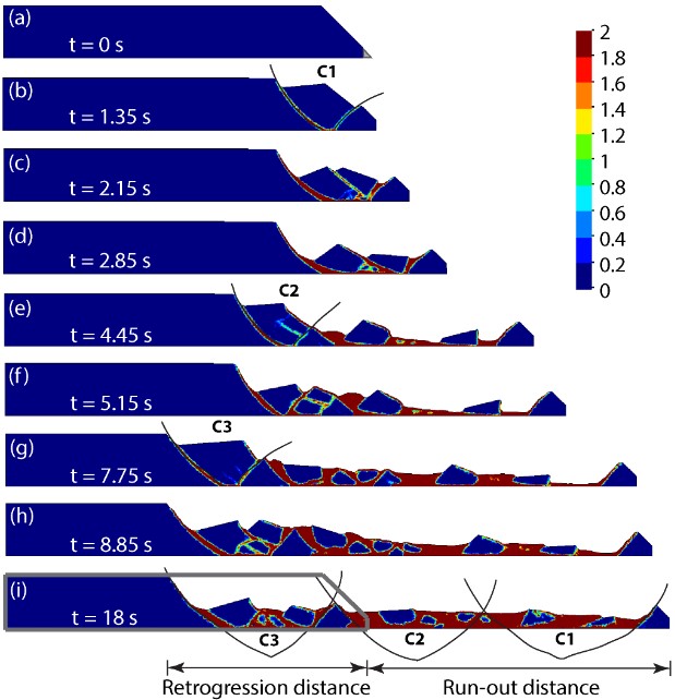
Figure 1: Failure mechanisms of an established slope. Colours are proportional to accumulated equivalent plastic strain
The collapse evolution of a column of initially undisturbed sensitive clay and remoulded sensitive clay are simulated by PFEM and compared in Fig. 2. For initially undisturbed sensitive clays, lifting the container results in localised shear bands in the final deposit, with some parts of the column remaining undisturbed throughout the failure process. The collapse of remoulded sensitive clay is quite different to the previous case of an undisturbed sample. Rather than fail progressively, nearly all the material experiences plastic deformation with that near the bottom showing the maximum equivalent plastic strain. The collapse of the column of remoulded clay results in a final deposit with a much smaller height and considerably larger width.
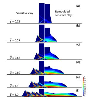
Figure 2: Collapse evolution processes of a column of an initially undisturbed sensitive clay and a remoulded sensitive clay. Colours are proportional to accumulated equivalent plastic strain
PHASE FIELD METHOD
Modelling the initiation and propagation of fracture is perhaps one of the most challenging problems in computational geomechanics. This is due to the fact that the extent and orientation of the fractures are not easy to predict in continuum calculations. To tackle this problem, a bespoke phase-field model has recently been implemented at the PRCGSE. This does not capture the crack surfaces explicitly. Instead, it smooths each discrete crack by introducing a phase field. Consequently, the model is free from discontinuities and can be implemented using standard finite element methods. The phase-field method has been applied to simulate fracture in rock (Zhang et al. 2017), as shown in Fig. 93 As the applied pressure increases, the wing cracks emerge first and develop steadily from the tips of the flaws due to tension. Further increase in pressure leads to the appearance of secondary cracks which are mode II cracks. When the pressure is sufficiently large, crack coalescence occurs at the zone between the flaws, which has also been observed in experimental tests.
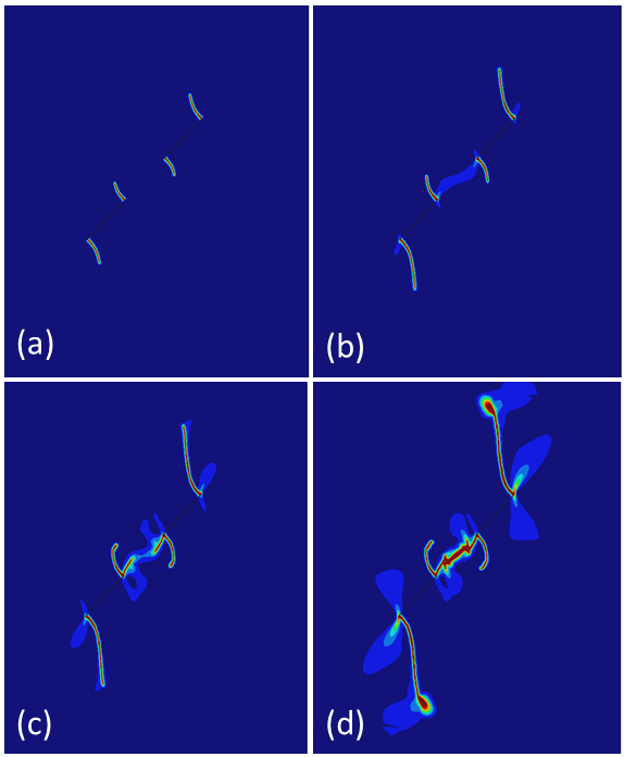
Figure 3: Crack evolution in a rock column under pressure: a) wing cracks, b) initiation of secondary cracks, c) further development of wing and secondary cracks, and d) crack coalescence
Enquiries

Enquiries
-
Centre Administrator
prcgse@newcastle.edu.au
The University of Newcastle acknowledges the traditional custodians of the lands within our footprint areas: Awabakal, Darkinjung, Biripai, Worimi, Wonnarua, and Eora Nations. We also pay respect to the wisdom of our Elders past and present.