Centre for Geotechnical Science and Engineering
Advanced Characterization Of Soft Soils
IN SITU TESTING
A crawler-mounted in situ testing facility capable of accessing difficult, soft and swampy terrain was commissioned at the UoN (Fig. 1a) in 2015. This rig provides Australian geotechnical research groups with access to a mobile state-of-the-art field testing facility which is capable of providing real time data on the behaviour of soft soils, facilitating the development and calibration of new theoretical design methods, as well as the advancement of novel tools and testing techniques. Aside from conventional testing and sampling equipment (seismic cone penetration, seismic flat dilatometer, field vane shear and in situ resistivity), the facility has been customised to accommodate non-standard testing. An enlarged opening in the floor of the crawler permits the use of wider, non-conventional devices and provides access for load testing of plies and footings. The facility was customised to accommodate a bespoke vertical and torsional electro-mechanical actuator and separate conventional hydraulic rams, in order to provide the capability of finely-controlled vertical and torsional rate-dependent and cyclic testing.
Figure 2 shows results of simple in situ resistivity (or conductivity) tests in practice. Archie’s law is used in this figure to obtain a porosity profile for the soft soil deposits at the Ballina, NSW site by combining in situ bulk resistivity data obtained using a hydrostatic profile tool (HPT) and a few pore fluid conductivity values measured in the laboratory. Experimental results give a formation factor F=3 for the entire soil profile. The parameter m was found to vary exponentially with the pore fluid conductivity, whereas the parameter a was assumed constant (a=1). The good agreement between the estimates form Archie’s law, and the values measured in the laboratory using high-quality specimens, demonstrate the reliability of this simple technique for the characterization of soft estuarine deposits.
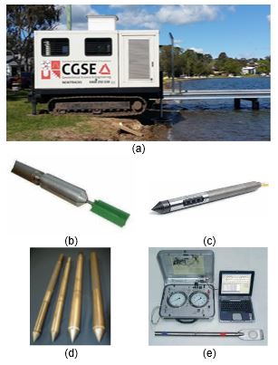
Figure 1: (a) Crawler-mounted in situ testing facility (b) Field shear vane (VS) (c) Hydraulic Profiling Tool (HPT) (d) Conventional Cone Penetrometers (CPT and CPTu) (e) Seismic Dilatometer (SDMT)
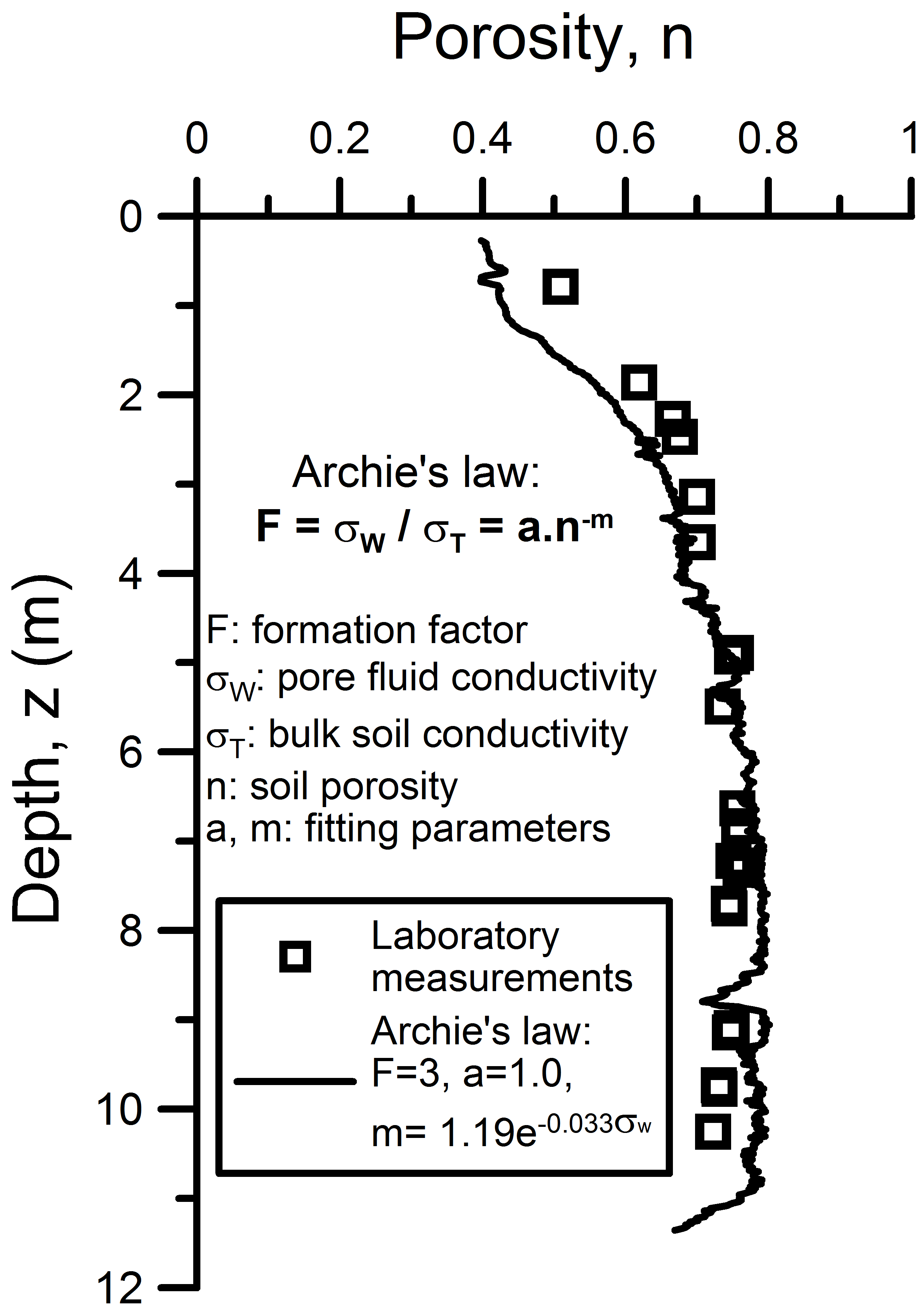
Figure 2: Estimated porosity using in situ resistivity measurements
HIGH QUALITY SAMPLING
Understanding the mechanical behaviour of soft soils requires high-quality soil samples for laboratory testing. However, these are difficult to obtain using available commercial methods like Shelby tubes (the most common technique used in practice) due to the important sample disturbance associated with this type of tube sampler.
Two high-quality sampling techniques, a fixed-piston sampler and a block sampler, have been incorporated into the arsenal of sampling methods available at the UoN. The first one is a hydraulic fixed-piston sampler (89 mm in diameter), able to retrieve specimens with excellent and good to fair quality in soft clays as recently demonstrated by Pineda et al. (2016a, b). As schematically shown in Fig. 3, the presence of an internal fixed piston helps to prevent the entrance of disturbed soil during lowering to the sampling depth. An internal thin walled tube is pushed into the ground using an inner sampler head via hydraulic pressure. After full penetration, the hydraulic fluid flows up (through the hollow piston rod) and down (through the cutting toe) to ensure the same static pressure inside the sampler and at the bottom base. This helps to minimize suction at the bottom of the sampler during withdrawal. Computer axial tomography (CAT) scans of tube specimens of Ballina clay (Fig. 4) show that specimens retrieved with the fixed-piston sampler are less disturbed than those in Shelby tubes.
Block sampling, which overcomes the problem of sampling disturbance caused by tube sampling, is not common in practice (not even in research) due to its cost. An alternative to tube samplers is the mini block sampler (Fig. 5a), a smaller version of the original Sherbrooke sampler, developed at the Norwegian Geotechnical Institute NGI, which seems to be a cost-effective option for research as well as industry use. This sampling technique is able to retrieve cylindrical specimens (160 mm in diameter and 300 mm in height) of the highest quality in complex soft soils deposits. It requires drilling of a 200 mm borehole which matches with standard drilling methods used in geotechnical practice. The sampler carves a cylindrical block specimen using 3 circumferential blades (spaced at 120º), in combination with 3 annular cutters, that carve a 50 mm wide slot around the specimen (Fig. 5b). When a sample of around 300 mm is carved, the 3 bottom blades are activated by means of a horizontal diaphragm in order to cut the base of the specimen. The horizontal cutters provide support to the specimen when it is lifted to the ground surface. At the ground surface, the sample is covered with plastic film and aluminium foil (Fig. 6) and then coated with layers of paraffin wax before being placed in a container packed with damp sawdust or other suitable material for shipping to the laboratory.
The use of either the fixed-piston sampler or the mini block sampler will have a positive impact on professional practice by reducing the uncertainty associated with the quality of the soil parameters used in geotechnical design.
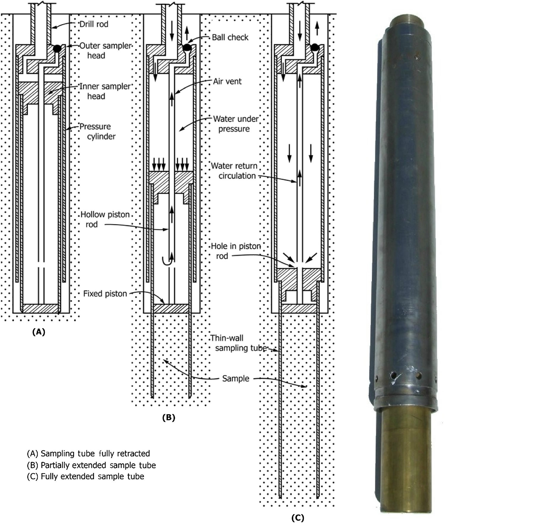
Figure 3: Fixed-piston sampler (ASTM D6519–08)
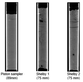
Figure 4: CAT scans of fixed-piston and Shelby samples
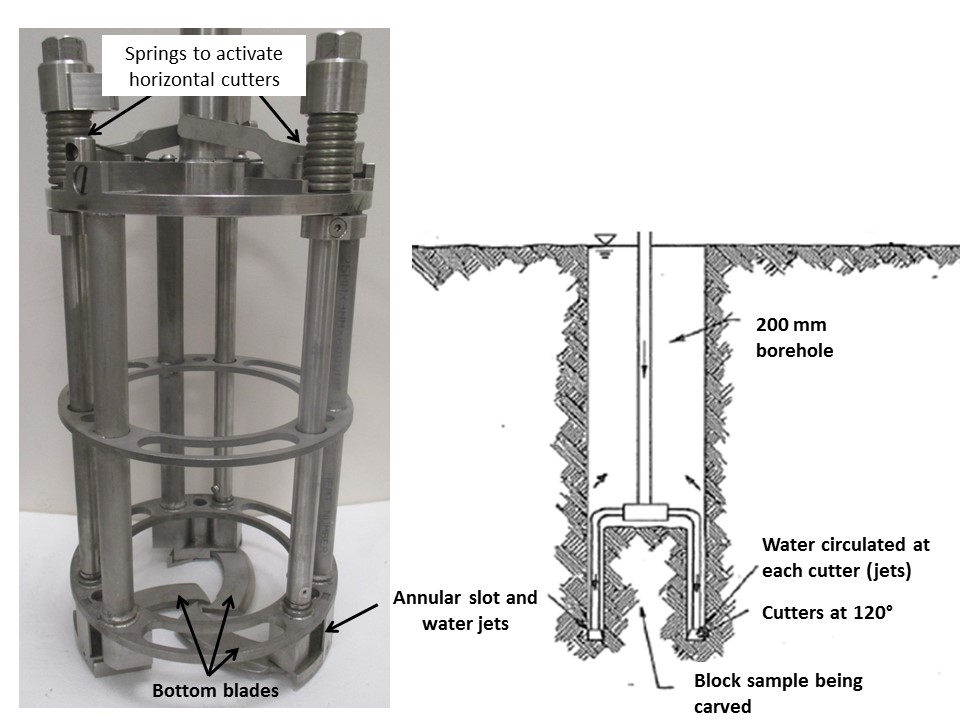
Figure 5: (a) Mini block sampler (b) Operational principle
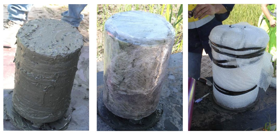
Figure 6: Ballina clay specimens retrieved with the Sherbrooke sampler
ADVANCED LABORATORY TESTING
The particular characteristics of natural soft clays (very low in situ stresses and undrained shear strength, high compressibility, presence of electrolytes in the pore fluid, presence of organic matter and expansive minerals as well as weak cementation) pose a number of serious challenges which many soil mechanics laboratories cannot handle. Modified guidelines have been implemented at the UoN for this purpose as summarized in Pineda et al. (2014). A crucial aspect, commonly neglected, is related to the chemical interaction between the pore fluid constituents and the solid phase in natural soft clays. Measurement and control of the soil’s electrical conductivity (EC) is relevant in the case of natural clays coming from estuaries and river systems where the pore water is saline. Sampling natural water for use in laboratory tests has limitations because sulphates in the water can oxidise to acid and slimes can form over time, both of which can affect the soil behaviour. A compromise is to prepare artificial saline solutions (homoionic solutions) in the laboratory. The use of saline solutions during mechanical tests (oedometer and triaxial tests) is, however, not straightforward and requires modification of conventional systems, to prevent changes in the pore water electrolyte that are induced by corrosion of laboratory devices and soil oxidation due to the exposure to oxygen.
A new oedometer cell was developed at the UoN to overcome this problem (Fig. 7). It is made of stainless steel (including valves and fittings) to avoid corrosion. The cell uses a 1mm-thick oedometer ring which is gently pushed into the soil mass to minimize soil disturbance. Bender element transducers are used to monitor the evolution of the shear wave velocity Vs, during loading. The oedometer cell works as a closed system (the soil specimen is isolated from the atmosphere) which allows the control and measurement of the electrical conductivity of the pore fluid. This cell is being used for performing constant rate of strain (CRS) tests (Fig. 7), conventional incremental loading (IL) and creep tests on soft soils. Figure 8 shows typical CRS oedometer results obtained on natural Ballina clay specimens. Synthetic pore fluid was employed to replicate the salinity of the natural soft clay. The CRS test results show a strong non-linearity of the compressibility curve, a typical feature of natural soft soils that implies the compression index Cc varies with the stress level. Moreover, the very good agreement observed between laboratory and in situ shear wave velocities for sꞌv= sꞌv-in situ gives confidence in the veracity of the laboratory results, which may be used in combination with in situ tests to characterize the complex behaviour of soft soil deposits.
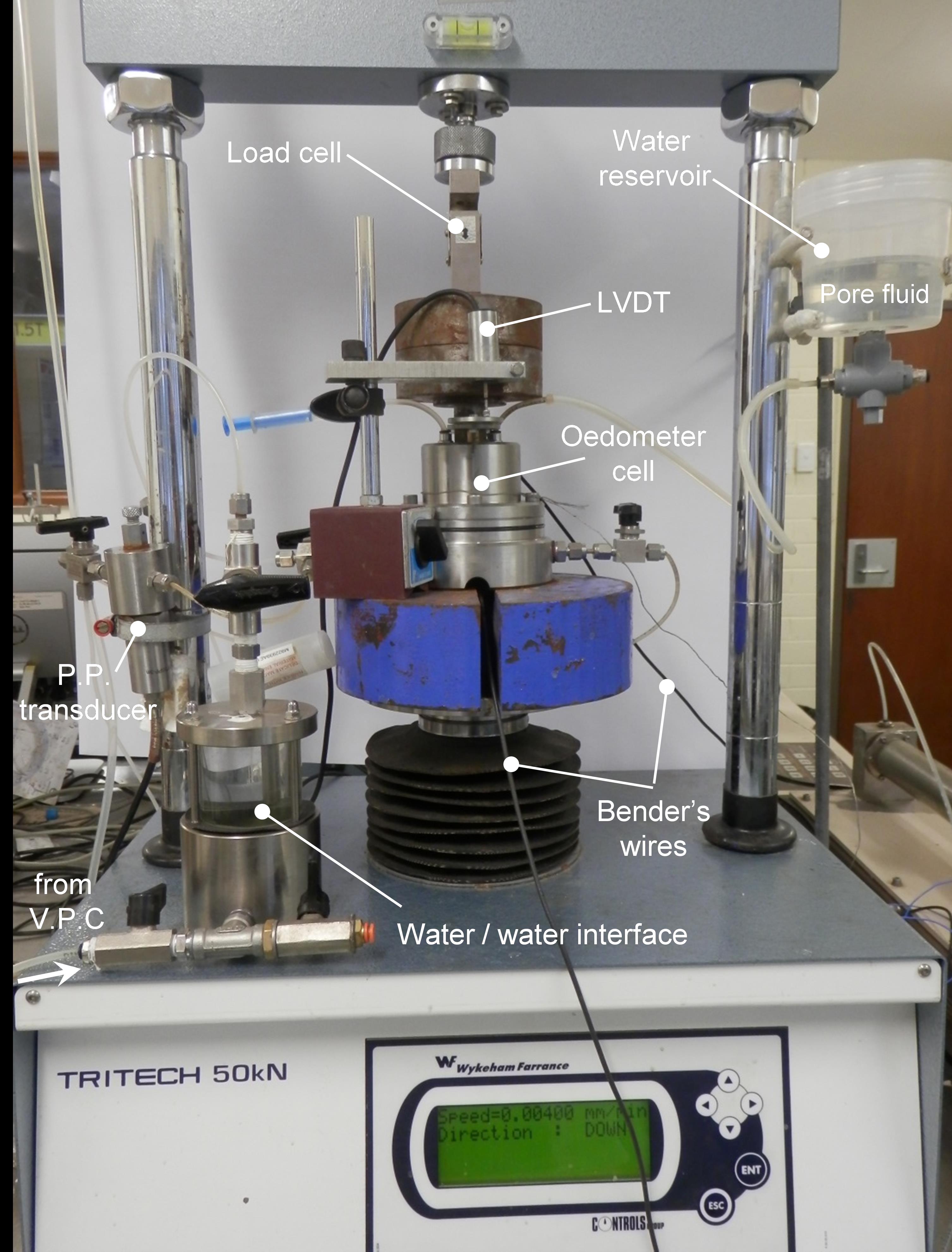
Figure 7: CRS oedometer system
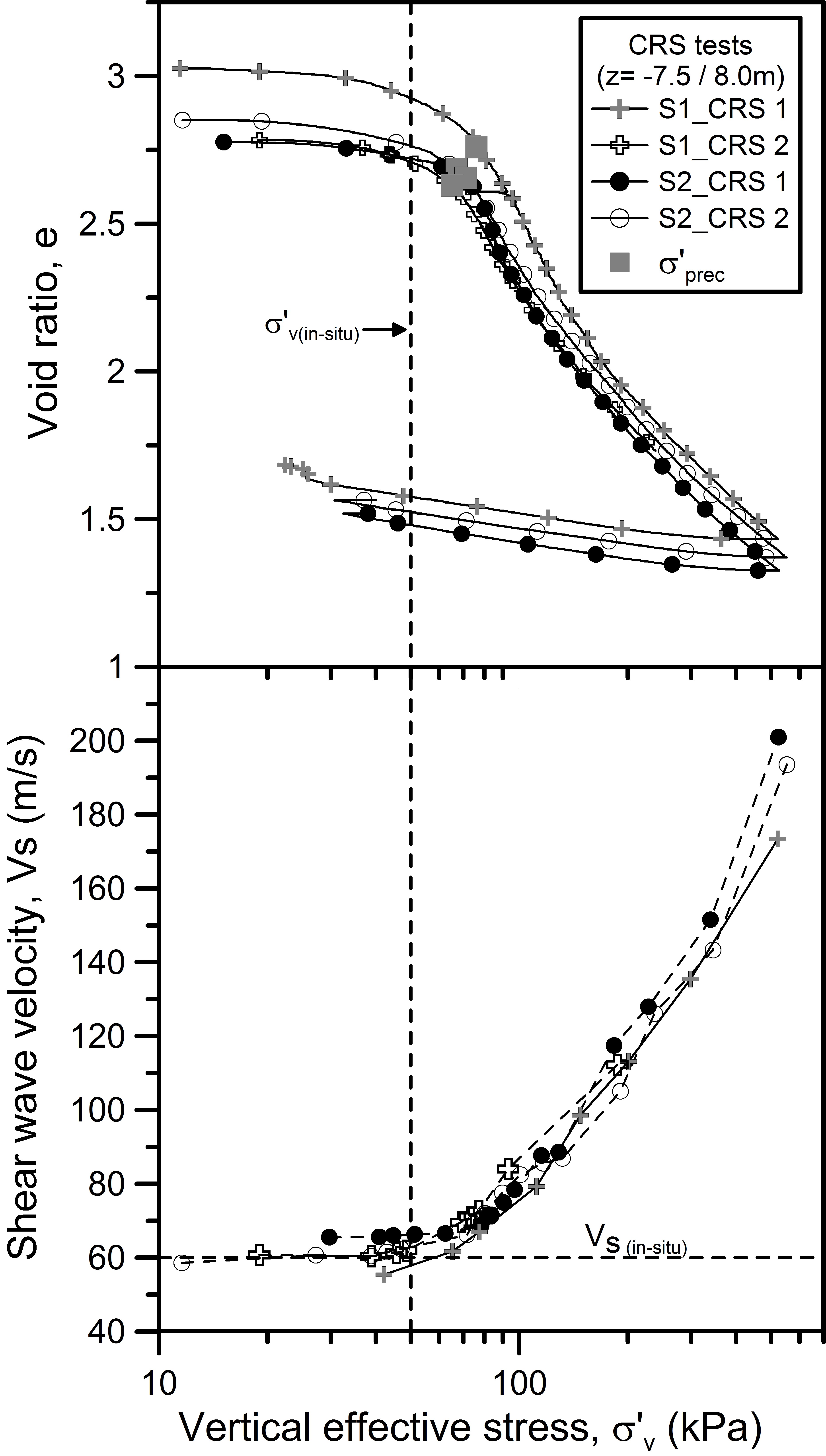
Figure 8: CRS test results obtained on Ballina clay
Hydraulic stress-path triaxial apparatuses developed at Imperial College, UK (Fig. 9), which are able to control small stress and/or strain increments with high accuracy, are used at the UoN to study the mechanical behaviour of soft soils under a wide spectrum of loading paths (Fig. 9). These devices include internal instrumentation (LVDTs) for estimating axial and radial deformations as well as bender element transducers for measuring the small-strain stiffness. Pedestals, top caps, fittings, valves and auxiliary devices are made of stainless steel in order to control the pore fluid chemistry during testing. An example of the performance of the triaxial device is given in Fig. 10. It shows the stress paths followed by Ballina clay specimens subjected to anisotropically consolidated undrained triaxial compression (TC) and extension (TE) tests (Pineda et al., 2016a; Kelly et al., 2017). The triaxial results show good consistency and indicate asymmetry of the yield locus about the isotropic line, as expected in natural soft soils.
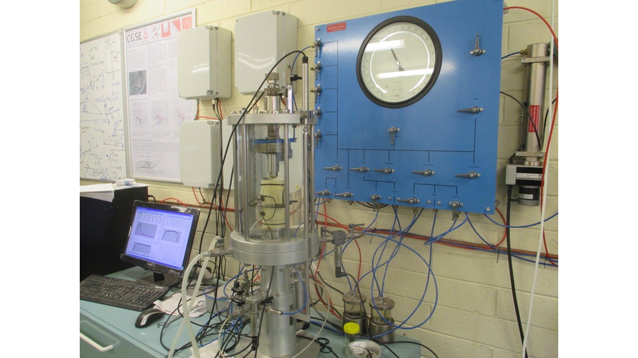
Figure 9: IC stress-path triaxial apparatus
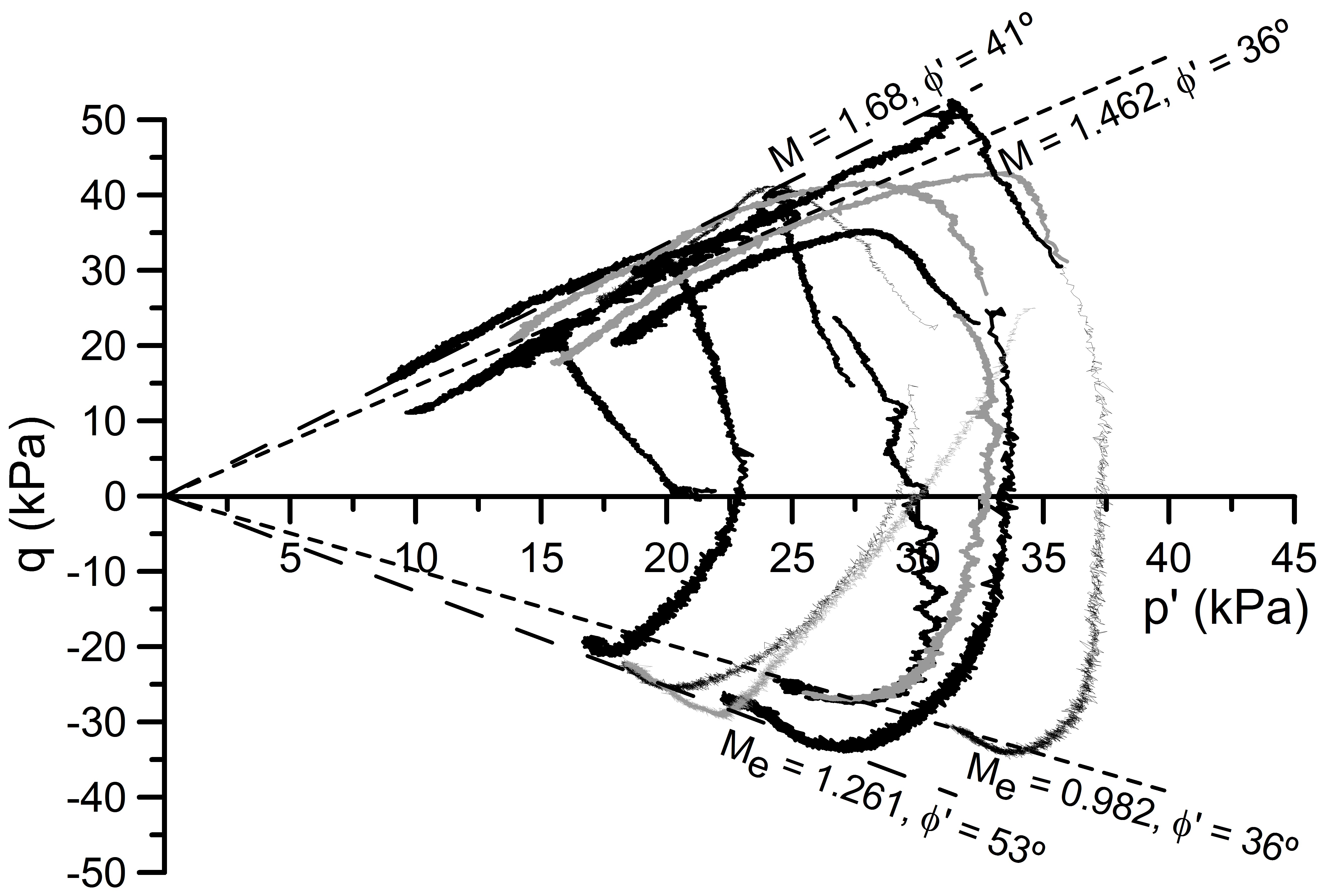
Figure 10: Undrained triaxial compression and triaxial extension tests on Ballina clay
The rotation of principal stresses is a phenomenon that occurs often in infrastructure projects such as embankments, shallow footings and onshore and offshore infrastructure subjected to cyclic and multi-directional loading. A torsional hollow cylinder apparatus has been recently acquired by the UoN with the aim of studying the rotation of the principal stresses in soils. This device (Fig. 11), is currently being used to study the rotation of principal stresses underneath embankments and shallow footings founded on Ballina clay.
MICROSTRUCTURAL ANALYSIS
In the UoN laboratory, Mercury intrusion porosimetry (MIP) and Scanning Electron Microscopy (SEM) are used to characterize the soil fabric. The pore size density function (PSD) obtained from MIP tests (de/dlog(x)) provides information on predominant pore sizes, their frequency and how these pores evolve when subjected to specific loading paths. Figure 12 shows results of three MIP tests performed on Ballina clay using the AutoPore IV 9500 apparatus. Three soil states are represented in this figure: the intact (natural) state, the soil state after CRS loading and the soil state after undrained triaxial compression. It can be seen that CRS loading results in a decrease in the predominant pore sizes, whereas undrained triaxial compression tends to increase the dominant pore size (peak) caused by soil dilation inside the shear band.
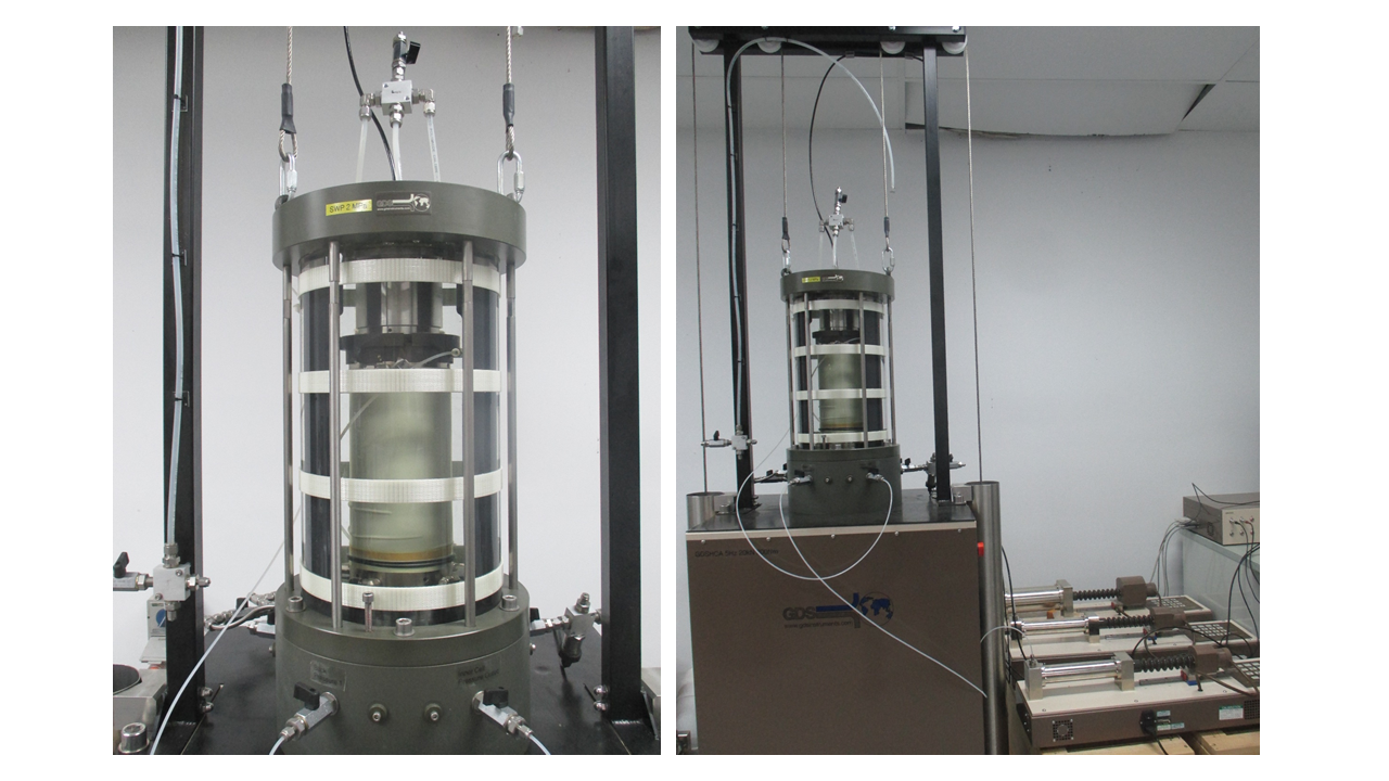
Figure 11: GDS Hollow cylinder apparatus
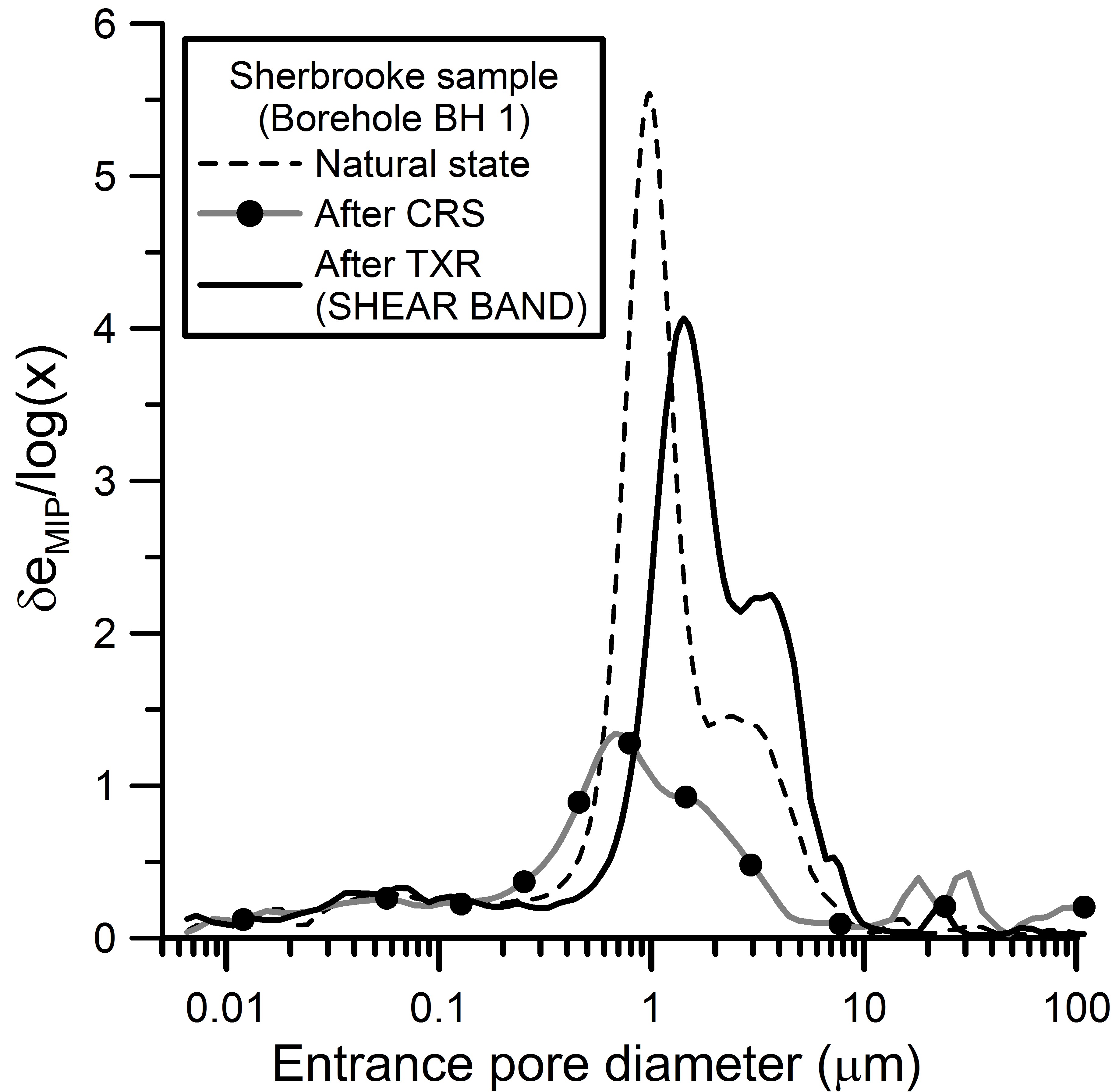
Figure 12: MIP results for Ballina clay
Enquiries

Enquiries
-
Centre Administrator
prcgse@newcastle.edu.au
The University of Newcastle acknowledges the traditional custodians of the lands within our footprint areas: Awabakal, Darkinjung, Biripai, Worimi, Wonnarua, and Eora Nations. We also pay respect to the wisdom of our Elders past and present.